Applications

From portal frames to offshore wind, each with its own concerns

The same platform, completely different concerns per engineering domain: building structures worry about inter-storey drift and overall stability, bridges about moving loads and fatigue, offshore wind about frequency separation, geotechnical and underground works about deformation control, earthquake engineering about nonlinear response. Below, organised by engineering type — buildings, bridges, offshore wind, geotechnical, underground and seismic engineering — is how you would actually put the tool to work. Not a case gallery, but how you would use it.

Not a case gallery.Kavvo has no released version and no real client projects yet — inventing a few "factory project" stories would be easy, but it would be fiction. What follows are modeling paths organized by structure type: how you would put the tool to work, and which step is easiest to get wrong.

Portal frame industrial building: Tapered members, lightweight roof, wind uplift governed
01Tapered members, lightweight roof, wind uplift governed

Portal frame industrial building

Structure
Single-storey portal frame with tapered columns and rafters, plus purlins, column ties and roof bracing
Analysis types
Static (dead / live / wind / crane) · Modal · Buckling (tapered column stability)
Outputs
Internal force envelopes, column-top drift, purlin and bracing forces, base reactions, calculation report

Common pitfalls

  • Model tapered members in segments — a single prismatic member overestimates stiffness
  • Wind pressure coefficients must be zoned (windward / leeward / roof zones); a single value will not do
  • Do not assume stressed-skin (diaphragm) action by default — only with reliable evidence for the sheeting and its fixings

Modelling sequence and three pitfalls →

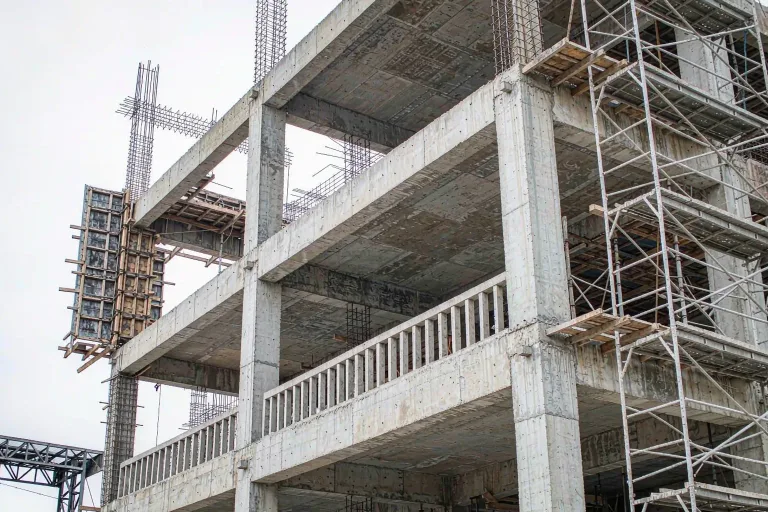
Multi-storey frame: Inter-storey drift and floor diaphragm assumptions
02Inter-storey drift and floor diaphragm assumptions

Multi-storey frame

Structure
RC or steel frame with rigid beam-column joints, floors working with the frame
Analysis types
Static · Modal · Response spectrum · Pushover · Time-history
Outputs
Inter-storey drift, member forces, reinforcement design basis, performance point, calculation report

Common pitfalls

  • Rigid diaphragm assumptions hold only for regular structures; with large openings or long cantilevers, model the floors as flexible
  • Short-column effects come from infill wall restraint — if the walls are not in the model, judge them by hand
  • Concrete tension stiffening must not be skipped — cracked beam-end stiffness and natural periods both change

Concrete and confined concrete →

Long-span space frames and roofs: Overall stability and thermal actions
03Overall stability and thermal actions

Long-span space frames and roofs

Structure
Double-layer space grids, tubular trusses and beam-string structures, mostly pin-jointed
Analysis types
Static · Buckling (overall stability) · Modal · Geometric nonlinearity
Outputs
Member forces and stress ratios, joint displacements, overall stability factor, support reactions

Common pitfalls

  • Members are pinned by assumption; verify joint moments separately — do not detail joints straight from pin-jointed results
  • Thermal actions cannot be skipped: temperature forces in long-span structures are often of the same order as dead load
  • Second-order effects are mandatory for long spans; the linear buckling factor is only an upper bound

Choosing a solver →

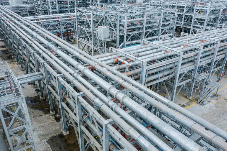
Equipment supports and pipe racks: Equipment resonance and thermal expansion thrusts
04Equipment resonance and thermal expansion thrusts

Equipment supports and pipe racks

Structure
Steel support frames, multi-tier pipe racks, equipment foundations and pedestals
Analysis types
Static (equipment loads / pipe thrusts) · Modal (frequency separation) · Seismic
Outputs
Support forces, structural frequencies, anchor bolt and foundation reactions, displacements

Common pitfalls

  • Check dynamic equipment loads against resonance: structural frequencies should stay clear of the equipment's operating frequency
  • Pipe thermal expansion thrusts are often missed — they can govern support sizing
  • Anchor bolt reactions feed foundation design; uplift load cases must be extracted separately

Units and quantities →

Steel truss and girder bridges: Moving loads and fatigue
05Moving loads and fatigue

Steel truss and girder bridges

Structure
Steel trusses, plate girders and composite girders, with gusset plates and connections
Analysis types
Static + moving loads · Stability · Modal · Fatigue (stress ranges)
Outputs
Force envelopes, deflections, stability checks, fatigue stress ranges, bearing reactions

Common pitfalls

  • Moving loads need influence-line loading; hand-picking critical positions almost always goes wrong
  • Fatigue often governs — stress ranges must come from the actual traffic spectrum, not strength checks alone
  • Temperature and bearing restraint determine secondary forces; a wrong bearing assumption skews every result

Steel and reinforcement →

Offshore wind foundations: Frequency separation, pile–soil interaction, combined wave and current
06Frequency separation, pile–soil interaction, combined wave and current

Offshore wind foundations

On the roadmap (phase C1, sequential multiphysics iteration) — the current release does not include offshore wind coupled analysis.

Structure
Jackets, monopiles, floating foundations
Analysis types
Static + modal · Time-history (waves) · Pile–soil interaction · Fatigue
Outputs
Structural frequencies (clear of 1P / 3P bands), member stress ratios, pile reactions, fatigue life

Common pitfalls

  • Frequencies must avoid the rotor 1P and blade 3P bands — this often governs the design more than strength does
  • Model pile–soil interaction with p-y springs, not fixed bases — soil flexibility directly shifts frequencies
  • Apply waves and current jointly, and use sections net of the corrosion allowance

Choosing a solver →
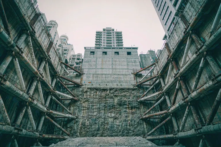
Deep excavation and retaining systems: Deformation control, staged excavation
07Deformation control, staged excavation

Deep excavation and retaining systems

Structure
Deep excavation support systems: diaphragm walls or bored pile walls with internal struts or ground anchors, multi-level strutting in staged excavation
Analysis types
Excavation stage simulation (stepwise activate / deactivate) · Retaining structure forces and deflections · Base heave and stability
Outputs
Wall horizontal displacements, strut axial forces, ground surface settlements behind the wall, calculation report

Common pitfalls

  • Simulate excavation in stages, never in one step — the installation timing of each strutting level changes the load path
  • The soil constitutive model directly sets the deformation magnitude: linear elasticity markedly underestimates movements — soft soils need a model capturing plastic behaviour
  • Strut preload and the removal sequence affect the force envelope — do not omit the strut-removal stages

Geotechnical material selection →

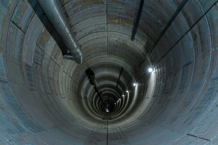
Tunnel lining: Soil–structure interaction, load–structure method
08Soil–structure interaction, load–structure method

Tunnel lining

Structure
Composite tunnel lining sections: primary support + secondary lining, with rock mass classification and load models
Analysis types
Section verification by the load–structure method · Rock pressure load cases · Seismic case (ground displacement method)
Outputs
Lining bending moment and axial force diagrams, safety factor verification, calculation report

Common pitfalls

  • The load–structure method and the soil–structure (convergence–confinement) approach are two distinct routes; be clear which one your verification basis follows
  • Rock-mass subgrade reaction must not be applied over the full ring — only along segments in contact with the ground and in compression
  • The seismic incident angle and how ground displacements are imposed strongly affect the response magnitude

Choosing a solver →

Seismic isolation and energy dissipation: Period shift, energy dissipation checks
09Period shift, energy dissipation checks

Seismic isolation and energy dissipation

Structure
Base-isolated or energy-dissipating structures: lead-rubber bearings / viscous dampers + superstructure
Analysis types
Nonlinear time history (multiple records, bi- / tri-directional input) · Bearing compression–tension and displacement checks · Damping reduction factors and storey response comparison
Outputs
Bearing displacements and forces, storey shear comparison envelopes, calculation report

Common pitfalls

  • Isolation models must take unreduced ground motions as input — the spectrum reduction convention differs from the fixed-base model
  • Bearing tension checks are often missed: vertical earthquake and overturning load cases can put bearings in tension
  • Design forces for damper connections and joints should be taken at the damper force corresponding to at least 1.2 times the rated stroke

Units and quantities →

Verification cases: 3 published, the rest tracking releases

The only credible evidence that a finite element solver is right is comparison against analytical solutions, tests and independent implementations. Every published case below includes model files, analysis settings, results and errors — download them and recompute. Cases not yet done are listed as they are; nothing is quietly removed.

CaseBenchmarkChecksStatus
Cantilever beam in bending →Analytical solution δ=PL³/3EI (mechanics of materials)Tip deflection, section moment of inertiaPublished
Portal frame →Nonlinear pushover self-consistency (yield mechanism / equilibrium checks)Base shear curve, plastic hinge locationsPublished
Four-storey two-bay frame →Eigenvalues and storey drift distributionFundamental period, mode shapes, pushover mechanismPublished
Cantilever column bucklingEuler critical load analytical solutionFirst buckling eigenvalue and mode shapePending M1
SDOF time historyNewmark-β hand calculation / textbook examplePeak and phase of the displacement historyPending M1
Independent comparison with commercial softwareThird-party results from independent modelling and independent solvingForce envelopes, column-top displacement, natural periodsPending M1

Every published case ships with model files, analysis settings, results and errors — a comparison figure alone is not verification, because a figure cannot show which parameters you changed. See the full case archive →

Your structure is not on the list?

Beams, columns, braces, trusses, plates and shells, cables — all modelable. The scenarios above are just the most common ones. Tell us about your structure and we can work out how to model it together.